Radio Gramophone Development P.A. 1008
Manufacturer:
Radio Gramophone DevelopmentModel:
P.A. 1008Country of Manufacture:
United KingdomMicrophone Type:
RibbonPolar Pattern:
Figure 8Production Start Year:
1947Rarity:
5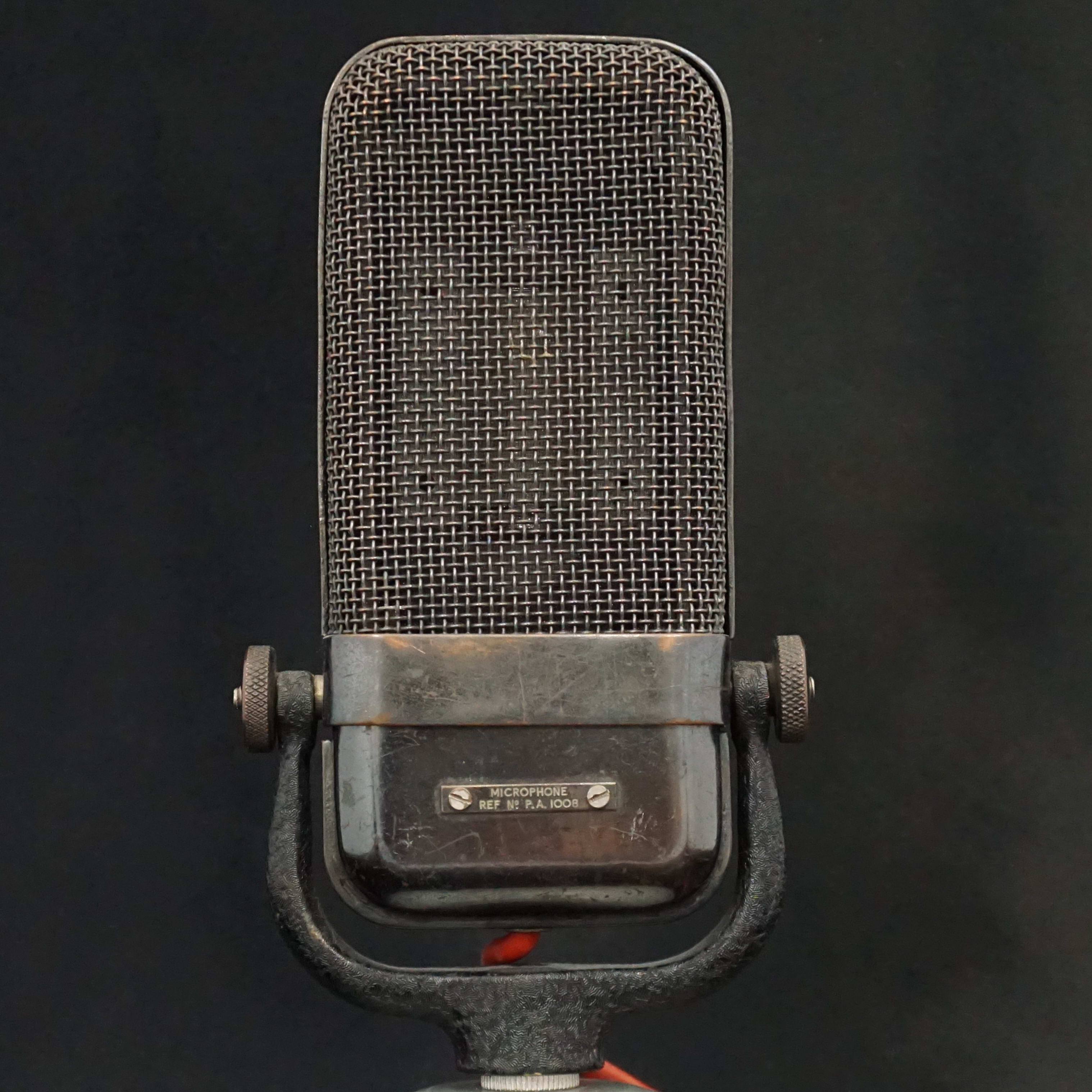
Audio Recordings:
Speech (male) recorded with the RGD ribbon microphone.
Multiple quality options available
Nylon string guitar recorded with the RGD ribbon microphone.
Multiple quality options available
Microphone History:
This microphone was designed and patented by H F Duffell and the Radio Gramophone Development Company Ltd. The patent was applied for in 1947 and awarded in 1950.
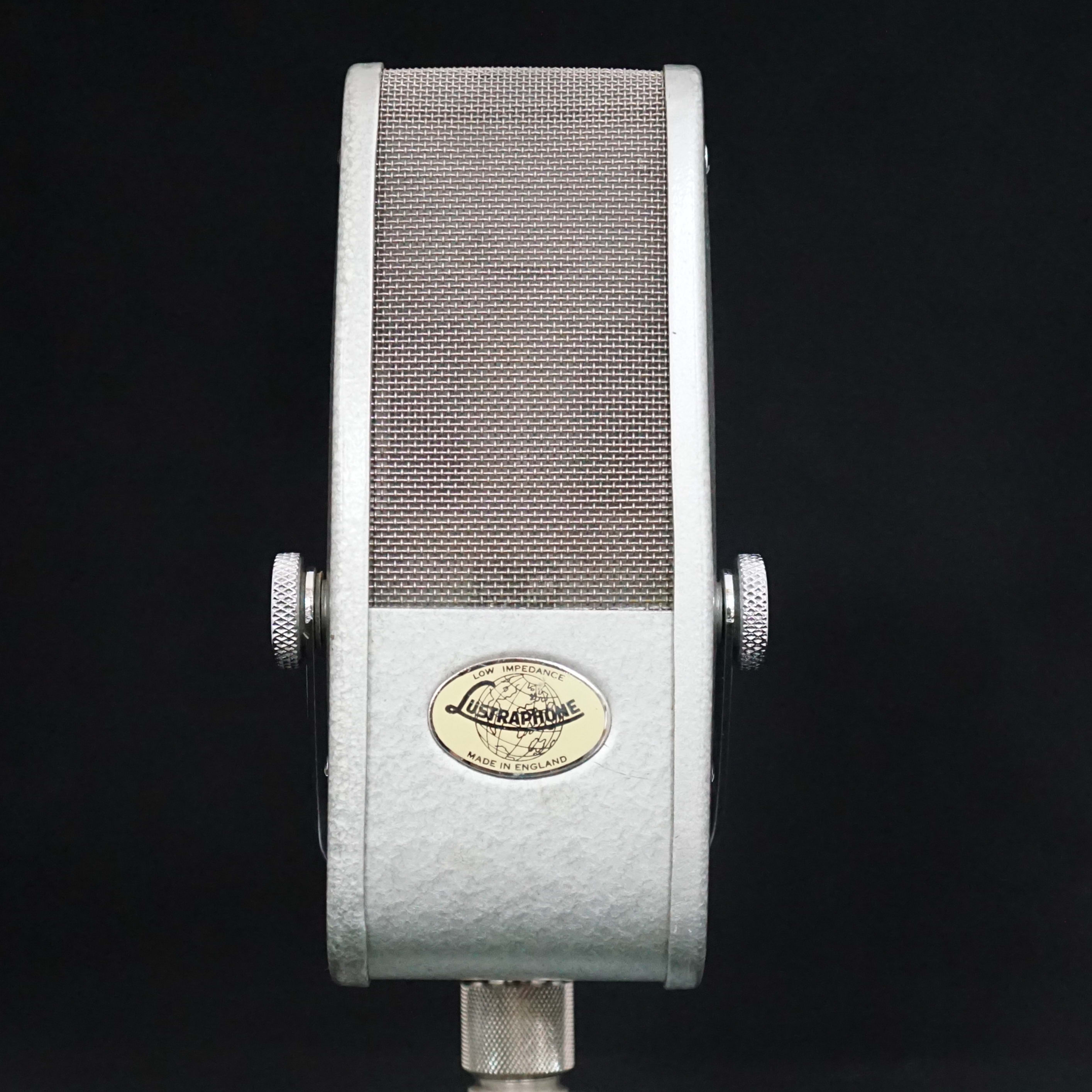
We have only ever seen one example of this microphone and so consider it to be extremely rare. It is made to a very high standard with a bronze plated brass body and cast brass yoke.
Technical Description:
MoMics View:
The RGD ribbon microphone has two innovative elements in its design. Firstly, the position of the magnetic poles may be adjusted by loosening and tightening two screws on each side of the motor. This means that the ribbon may be fitted and tuned in a wide gap, and then the poles are moved to the optimum positions to give the desired narrow gaps to each side of the ribbon. This ensures that the ribbon can move freely but also is exposed to the maximum magnetic field, which in turn maximises the output.
The second feature is in the transformer. Most designs use enamel wire for the primary winding but the transformer in this RGD microphone has a series of metal bars with a rectangular cross section, which are spaced out along the bobbin. The secondary is wound between these, and then the primary circuit completed by soldering bars across the primary hoops. (Please see the internal photos to see how this is achieved.) This approach minimises the primary winding resistance because the rectangular bar occupies the maximum cross sectional area in the transformer. (Circular section wire can in practice only occupy 80 to 90% of the area).
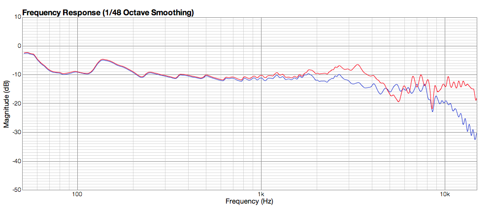
Despite these innovations, the magnetic field is rather weak and the output low. There is a pronounced difference between the two sides of the microphone. The red line in the frequency response chart is for the front of the microphone (the side with the badge), and the blue line is the reverse.
Frequency Response: